How to Design a Machine Vision System Step by Step

To design a machine vision system, start from the use case and work backward. Choose the camera and lens for the number of pixels your model needs on the feature, light the part so the feature stands out from surface noise, then size the network, GPU and model input to keep up with the line. Roboflow handles training RF-DETR, building the pass/reject logic as a Workflow, and running it on a Roboflow Jetson device such as the RF-NX16 on the line.
In this guide, I’ll show you how to design a machine vision system for inspecting painted blocks on a conveyor. We’ll select a camera, lens, and lighting setup, then calculate the network bandwidth and GPU capacity needed to process the images. Along the way, I'll show you how focus, exposure time, and image resizing impact the visibility.
I use RF-DETR for detection and Roboflow Workflows (opens in a new tab) to connect image processing, predictions, and pass-or-reject outputs. You can follow the calculations to select components for your own inspection task, then test the setup with your parts and production conditions.
How the machine vision system choices depend on each other
A vision system's accuracy and speed depend on seven choices: the camera, lens, light, network, compute, pipeline and model. The model is only one of the seven, and the choices depend on each other, so a later choice can send you back to change an earlier one.
The lens forms the image on the camera's sensor, and the feature's contrast in that image depends on the light. The network carries each frame to the compute, where the pipeline passes it to the model. The model needs enough pixels and contrast on the feature, and those come from the camera, lens and light.
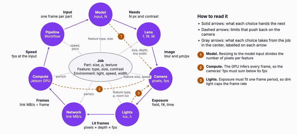
Three later choices can force you to change the camera: the model input, the GPU and the light.
- Shrinking the frame to the model's input size shrinks the feature too, so fewer pixels land on it.
- All the cameras share one GPU, so their frame rates must add up to less than the GPU can run.
- Each exposure has to fit in one frame period, so dim light can cap the frame rate.
The example job
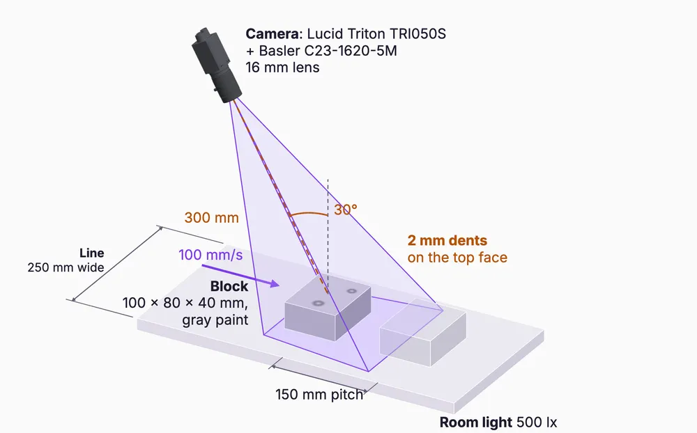
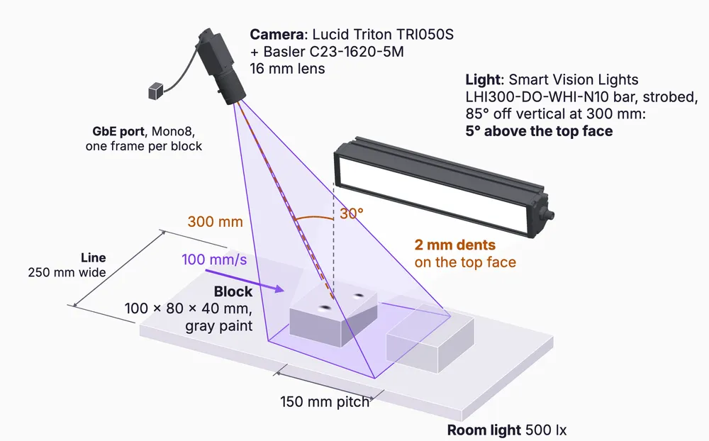
The example is a gray painted block on a conveyor. You want to find 2 mm dents in the paint on its top face.
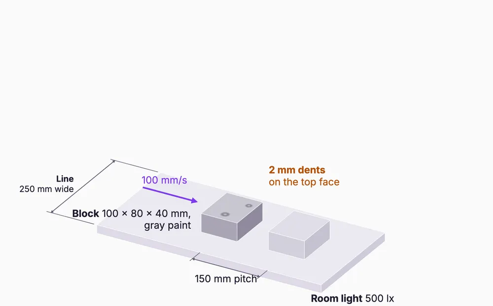
| Input | Value |
|---|---|
| Part | Gray painted block, 100 × 80 × 40 mm |
| Feature | 2 mm dents, walls about 3° steep |
| Surface | Smooth paint, 5% texture |
| View | 30° off vertical, 300 mm to the top face |
| Line | 100 mm/s, one block every 150 mm, 250 mm wide |
| Room light | 500 lx |
Choose the camera and lens
The camera and lens set what is in the frame and how many pixels land on the feature, so you choose them first.
Pixels on the feature
Start from the number of pixels that must cross the feature. The minimum is two (the Nyquist rate), and accuracy improves with more; the number you need depends on the model. This example uses 15 to classify the dent. With 15 pixels across a 2,000 µm dent, each pixel can cover at most 133 µm of the block.
Camera
For this job, pick the Lucid Triton TRI050S, a 5 MP mono GigE camera with a global shutter. It has 2448 × 2048 pixels, each 3.45 µm, and supports Power over Ethernet (PoE).
Lens
The lens has to fit the whole block in the frame. At 30° the block needs a field 125 mm wide, and at 300 mm that takes a focal length of 20.3 mm. Stock lenses come in steps, and each one works over a range of working distances:
| Focal length | Working distance range |
|---|---|
| 12 mm | 177 to 464 mm |
| 16 mm | 237 to 618 mm |
| 25 mm | 370 to 966 mm |
The 16 mm lens is the closest stock focal length that works at 300 mm. On the belt, which sits below the top face and is seen at 30°, its frame is 206.5 mm wide, inside the 250 mm line.
Pixels on the block
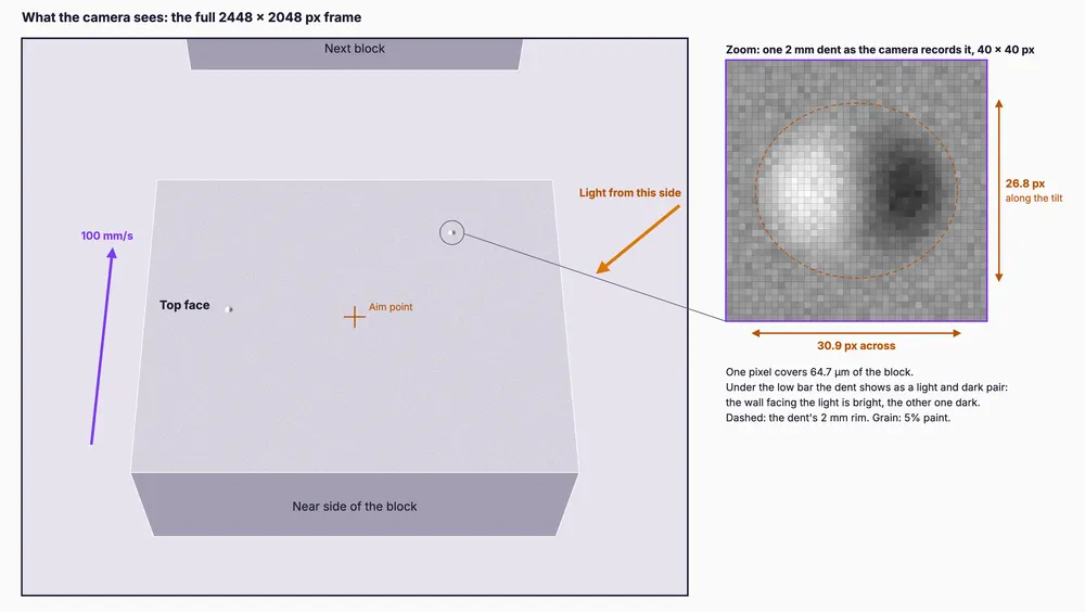
Each pixel covers 64.7 µm of the block, about half the 133 µm limit. Head on, a 2 mm dent would span 30.9 pixels. Viewed at 30° it is foreshortened to 26.8 pixels at the middle of the face, 30.5 at the near end and 23.7 at the far end.
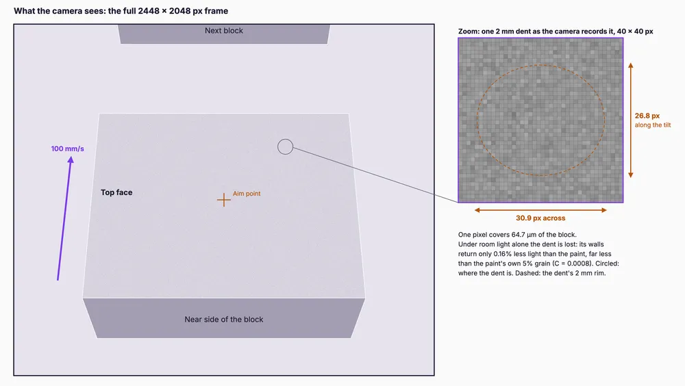
Under room light alone the dent is lost in the paint's 5% grain, because its walls return only 0.16% less light than the paint.
Check focus and sharpness
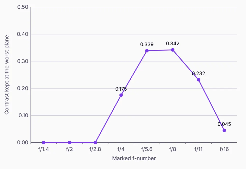
Blur lowers the contrast of fine detail. Seen at 30°, the top face spans 40 mm of depth, so with its middle in focus its ends sit 20 mm from the focus plane. Three kinds of blur add up:
| Blur | What it is | At f/6.70 |
|---|---|---|
| Diffraction | light spreading through the lens opening; it grows as you close the aperture | 1.19 px |
| Defocus | blur away from the focus plane; it shrinks as you close the aperture | 2.3 px at the ends of the face |
| Motion | how far the block moves during the 0.59 ms exposure | 0.9 px |
The modulation transfer function (MTF) is the share of contrast left after all blur, from 1 (all of it) to 0 (none). With the aperture wide open, defocus wipes out the contrast at the ends of the face, and with it closed far down, diffraction wipes it out. The far end keeps the most contrast near f/6.7, an MTF of 0.36, so this job uses f/6.70.
Light the part
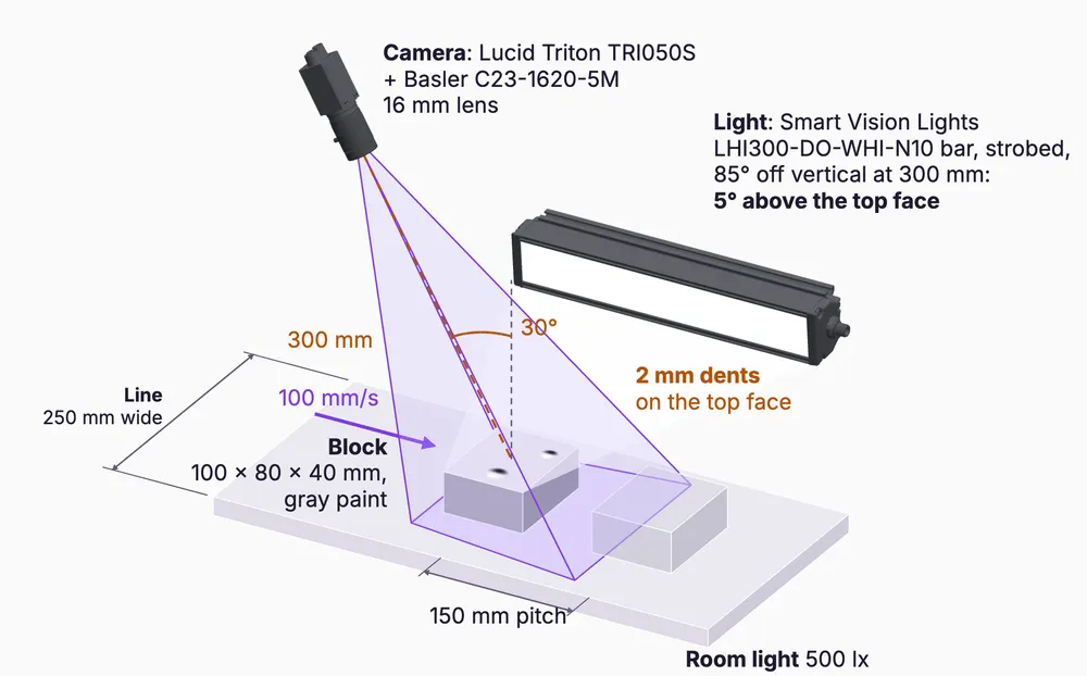
A dent is the same color as the paint, so it shows only as shading. Light from one side brightens the wall that faces it and shades the other, which turns the dent into a light and dark pair. A ring light around the part, the usual first choice for dents in matte paint, would light both walls equally, and with the camera tilted 30° it would also sit in the camera's line of sight, so this job uses a bar from one side.
The lower the bar, the darker the shaded wall:
| Bar angle off vertical | Dent contrast | Best margin moving |
|---|---|---|
| 45° | 0.028 | 0.18 |
| 70° | 0.081 | 0.45 |
| 80° | 0.180 | 0.85 |
| 82.5° | 0.257 | 1.08 |
| 85° | 0.441 | 1.51 |
The margin is the share of contrast the dent keeps after blur, divided by the least share it needs to stand above the noise (the next section works it out). A block passes when its margin is 1 or more. The moving block passes at 82.5° and 85°, and 85° gives the largest margin, 1.51 at the best exposure time.
Pick a Smart Vision Lights LHI300-DO-WHI-N10, a 290 × 40 mm white bar light, and strobe it in OverDrive mode. Mount it beside the conveyor, 85° off vertical (5° above the top face) and 300 mm from the face. It puts about 88,000 lx on the block.
Check signal to noise ratio
The sensor turns light into electrons. Under the bar, at f/6.70 and 0.59 ms, each pixel on the paint collects 2,596 electrons, and the dent changes that count by 1,589. Five sources of noise combine, as the square root of the sum of their squares:
| Source | Noise |
|---|---|
| Shot noise (light arrives as separate photons) | 50.9 e⁻ |
| Dark noise (the sensor's own electronics) | 2.5 e⁻ |
| Rounding to 8 bits | 3.4 e⁻ |
| Pixel-to-pixel gain (PRNU) | 15.1 e⁻ |
| Surface texture (the paint's 5% grain) | 129.8 e⁻ |
| Total | 140.3 e⁻ |
The paint's texture is the largest term. It grows with the light, so adding light cannot average it out. By the Rose criterion, the dent's step must be at least five times the noise. At the far end of the face the dent has to keep at least 0.224 of its contrast after blur, and with the block moving it keeps 0.332. That is a margin of 1.49 at the 0.59 ms exposure, so the moving block passes.
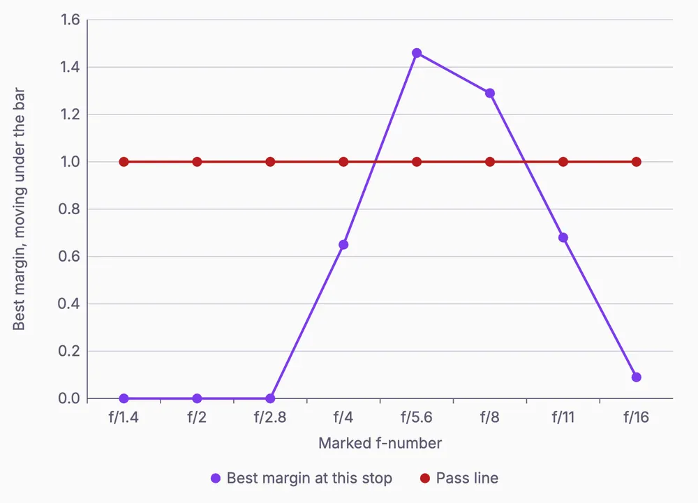
Closing the lens to f/11 for more depth of field costs light and adds diffraction, so the margin falls to 0.68 and the block fails.
Size the network
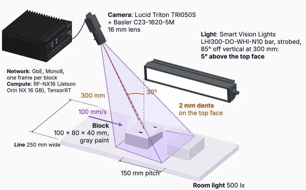
Machine vision cameras send frames uncompressed. One 2448 × 2048 frame in Mono8 (8 bits per pixel) is 5.01 MB, and a GbE link carries about 118 MB/s, which caps the camera at 23.5 fps.
| Link | Usable MB/s | Frames/s of a 5 MP Mono8 frame |
|---|---|---|
| GbE | 118 | 23.5 |
| 2.5 GbE | 295 | 58.8 |
| 5 GbE | 600 | 119.7 |
| 10 GbE | 1,180 | 235.4 |
With a trigger, the camera sends one frame per block. A block arrives every 1.5 s, so the job needs 0.67 frames per second, or 3.3 MB/s. To set up the trigger, see Trigger a Stream (opens in a new tab).
Pick the compute
The compute is an NVIDIA Jetson, and its GPU runs the model on every frame. Roboflow publishes inference benchmarks (opens in a new tab) for RF-DETR object detection on a Jetson Orin NX:
| RF-DETR detection | Native input | ONNX Runtime, images/s | TensorRT, images/s |
|---|---|---|---|
| Nano | 384 px | 21.2 | 78.5 |
| Small | 512 px | 13.9 | 52.5 |
| Medium | 576 px | 11.0 | 44.0 |
A larger input takes longer, and the time grows faster than the pixel count, because part of RF-DETR compares every patch of the image with every other. From a curve fitted to RF-DETR's published timings (opens in a new tab), Medium takes about 9.5 times as long at 1,376 px as at 576 px, so the Orin NX runs about 4.6 images a second with TensorRT.
Roboflow ships four Jetson devices:
| Device | Jetson module | GPU | Built for |
|---|---|---|---|
| AI1 | Jetson Orin NX 8GB | NVIDIA Ampere, 1,024 CUDA cores | 1 stream from its own 8 MP camera, lens and light |
| RF-NX16 | Jetson Orin NX 16GB | NVIDIA Ampere, 1,024 CUDA cores | 1 to 4 camera streams |
| RF-AGX64 | Jetson AGX Orin 64GB | NVIDIA Ampere, 2,048 CUDA cores | 4 or more camera streams, including line scan |
| RF-THOR128 | Jetson Thor T5000 | NVIDIA Blackwell, 2,560 CUDA cores | 8 or more camera streams, and vision-language models |
Pick the RF-NX16 with TensorRT. To set up a device, see Install on NVIDIA Jetson (opens in a new tab).
Build the pipeline
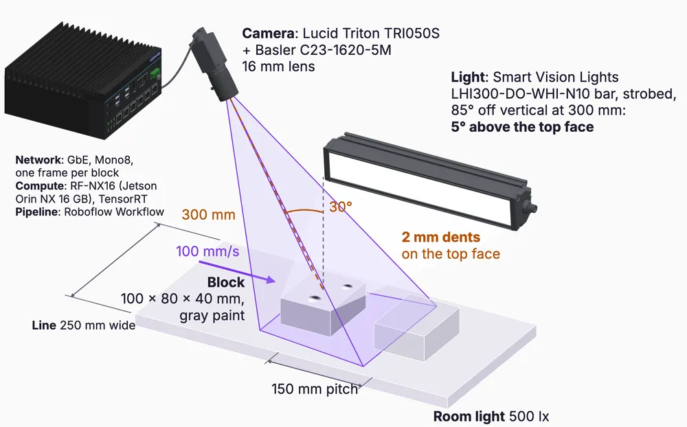
The pipeline is the software on the RF-NX16 that turns each frame into a decision. For each block it:
- Waits for the trigger and receives the frame.
- Prepares the frame and resizes it to the model input.
- Runs the model on the GPU.
- Keeps the detections you trust (ex: dents above a confidence threshold).
- Sends pass or reject to the line (ex: a PLC tag).
- Saves frames you want to review, so you can retrain on real misses.
You can build these steps as a Roboflow Workflow and run it on the RF-NX16. Workflow blocks that write to a PLC (ex: Modbus TCP or OPC UA) come with Enterprise plans. See Enterprise Integrations (opens in a new tab).
Each result is ready about 260 ms after the trigger: 0.59 ms of exposure, 42.5 ms to send the frame over GbE, and 217 ms on the GPU. The block moves 26 mm in that time, so the reject has to sit at least 26 mm downstream of the camera. Filtering the results and signaling the line add to this time, so measure them on the device.
Set the model input
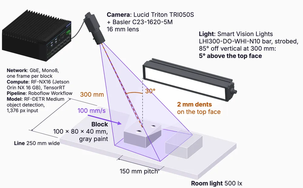
Most deployments resize the whole frame to the model's input size, which shrinks the feature by the same ratio. The camera puts 26.8 pixels on the dent across a 2448 px wide frame. To keep 15 of them, the input must be at least 56% of 2448, or 1,372 px. RF-DETR Medium takes inputs in steps of 32 px, so use 1,376 px.
| Model input | Pixels on feature | TensorRT, images/s |
|---|---|---|
| 576 px | 6.3 | 44.0 |
| 1,024 px | 11.2 | 11.0 |
| 1,376 px | 15.1 | 4.6 |
| 1,600 px | 17.5 | 2.8 |
If you tile or crop the frame instead of resizing it, the feature keeps its native pixel count.
The finished system
| Step | Choice | Deciding number |
|---|---|---|
| Camera and lens | Lucid Triton TRI050S mono, Basler C23-1620-5M 16 mm lens, 300 mm at 30° | 26.8 pixels on the feature |
| Lighting | Smart Vision Lights LHI300-DO-WHI-N10 bar, strobed, 85° off vertical; f/6.70, 0.59 ms | Margin 1.49 moving |
| Network | One GbE port, Mono8, one frame per block | 3.3 MB/s of 118 MB/s |
| Compute | RF-NX16 (Jetson Orin NX 16 GB), TensorRT | 4.6 fps against 0.67 needed |
| Pipeline | A Roboflow Workflow on the RF-NX16 | About 260 ms from trigger to result |
| Model | RF-DETR Medium object detection at a 1,376 px input | 15.1 pixels on the feature |
When a check fails
| Problem | What to change |
|---|---|
| Too few pixels on the feature | Use a longer lens or move closer, shrink the field of view, or add cameras |
| The part does not fit in view | Use a shorter lens or move back, or add cameras |
| Not enough contrast | For a dent or other change of shape, bring the light in at a lower angle |
| Not enough light | Add light, open the aperture, or match the light's color to the part |
| Too few frames | Trigger one frame per part, or use a faster link |
| The result comes too late | Move the reject farther downstream, or use a smaller model input |
| Too few pixels at the model input | Raise the input size, or tile or crop the frame |
Get started with Roboflow to train a defect detection model, build your inspection pipeline in Workflows, and validate its accuracy and speed on your production hardware.


