Line Scan Camera Defect Detection
 Mostafa IbrahimPublished Sep 9, 2026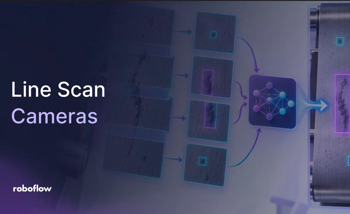
To detect defects in line scan camera images, build a three-block Roboflow Workflow. Image Slicer cuts the strip into 640×640 tiles with 25% overlap, RF-DETR runs on each tile, and Detections Stitch maps the boxes back onto the full strip and removes duplicates at tile edges. Fork the steel defect dataset from Roboflow Universe to try it, then swap in your own model and adjust the tile size and overlap for your line.
A small scratch can be easy to lose in a long inspection image. Line scan cameras capture continuous surfaces such as steel sheets, fabric rolls, and coated films as they move through production. Resizing an entire strip for object detection can shrink the defects you need to find, leaving too little detail for reliable detection.
With Roboflow Workflows, you can inspect these images in overlapping tiles. Image Slicer divides the strip into smaller regions, RF-DETR detects defects in each region, and Detections Stitch maps the predictions back to the original image and removes duplicate detections. Overlap gives the model more context around tile boundaries, where defects might otherwise be cut between slices.
In this tutorial, you’ll train a steel surface defect model, create a synthetic strip from test images, and build the tiled inference pipeline in Roboflow. You’ll configure tile size, overlap, and duplicate suppression, then inspect the combined results across the full strip. The same pattern can help preserve small-object detail in other large images, including aerial photos and high-resolution scans.
How Line Scan Cameras Work
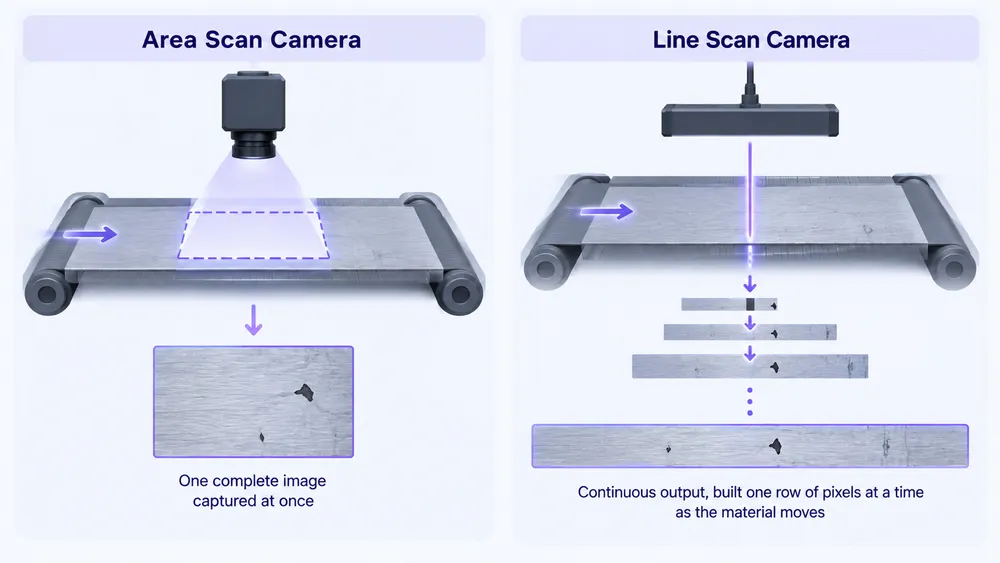
A standard area-scan camera captures a full rectangular frame in one shot, the way a phone camera takes a photo. A line scan camera works more like a flatbed scanner: it captures a single row of pixels at a time, and as the material moves past it on a conveyor, those rows stack together into a continuous strip image. The strip keeps growing as long as material keeps moving.
This is the standard approach for inspecting anything that comes as a continuous surface: steel sheets, fabric rolls, printed labels, coated films. The material doesn't come in discrete, neatly framed pieces, it rolls through, and a line scan camera matches that by producing one unbroken image rather than a sequence of separate snapshots.
The challenge is that detection models aren't built for images shaped like this. RF-DETR expects a roughly square input, a few hundred pixels per side depending on the model size. A line scan strip can be hundreds of thousands of pixels wide. Feeding it in directly isn't possible, and downscaling it to fit would shrink any defect to a few pixels, too small for the model to detect reliably.
Line Scan vs. Area Scan Cameras
| Feature | Line scan | Area scan |
|---|---|---|
| How it captures | Captures successive lines using relative motion | Captures two-dimensional frames |
| Output image shape | Fixed pixel count across each line; configurable image length | Rectangular frame with defined width and height |
| Best for | Continuous material, wide surfaces, and rotating parts | Discrete parts, assemblies, and stationary scenes |
| Motion handling | Synchronizes line acquisition with material movement | Uses exposure timing and, where needed, triggering or strobes |
| Lighting needs | Concentrated, uniform illumination along the scan line | Illumination across the inspection area |
| Typical cost and complexity | More synchronization work; can be economical for large, detailed scans | Often simpler for individual parts; cost depends on resolution and coverage |
Line Scan Camera Specs
- Line rate: The number of lines captured per second. Match it to material speed and the required sampling distance along the direction of travel.
- Pixels per line: The number of samples across the inspected surface. Combined with the field of view, this determines pixel spacing across the material.
- Encoder triggering: An encoder triggers acquisition after a defined travel distance, helping maintain consistent image geometry when conveyor speed changes.
- Line lighting: A dedicated light concentrates illumination along the scanned region. Brightness, uniformity, and lighting angle affect whether small defects remain visible during short exposures.
Why Line Scan Images Break Object Detection Models
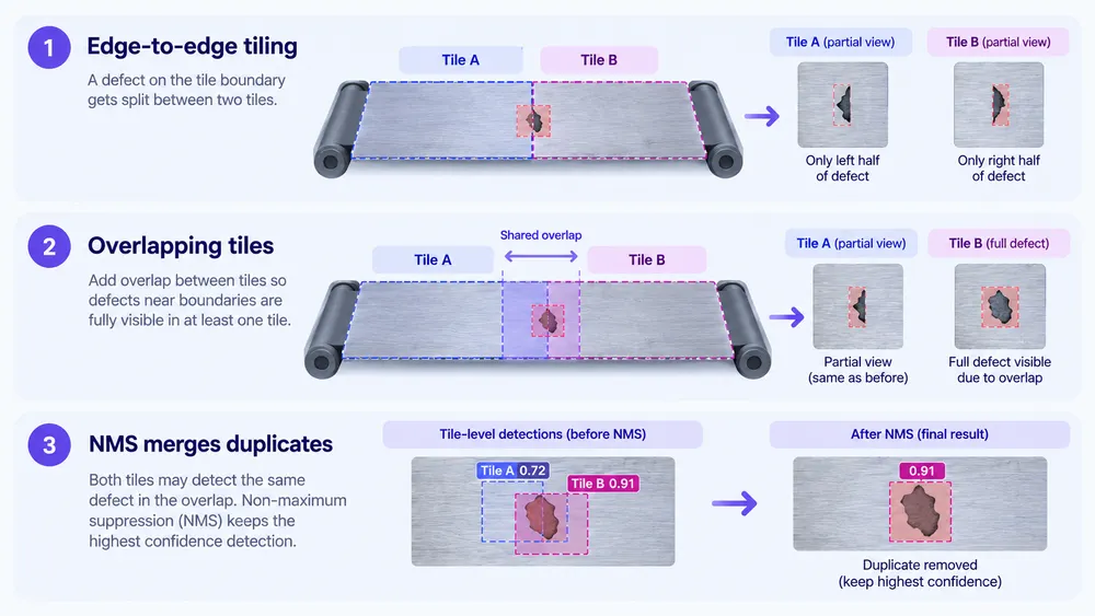
The natural answer is to slice the strip into smaller, model-sized tiles and run inference on each one separately. This works, until a defect lands exactly on the cut line between two tiles. When that happens, tile A gets the left half and tile B gets the right half. Neither tile sees the full defect, so the model either misses it entirely or produces two partial, low-confidence detections where there should be one.
The fix is to cut overlapping tiles instead of edge-to-edge ones. If each tile shares a margin of pixels with its neighbor, any defect sitting on a boundary appears fully inside at least one of the two overlapping tiles, guaranteeing the model sees the whole thing at least once.
But overlap introduces its own problem: defects inside the shared margin now get detected twice, once by each overlapping tile. Left unhandled, the output would show duplicate bounding boxes stacked on top of each other for every defect near a tile boundary. NMS (Non-Maximum Suppression) solves this by comparing all detections after inference, finding boxes that overlap beyond a set threshold, and keeping only the highest-confidence one while discarding the duplicate.
The Dataset
Fork the Steel Surface Defect Detection dataset from Roboflow Universe. It contains 1,900 images of hot-rolled steel strip surfaces with six defect classes.
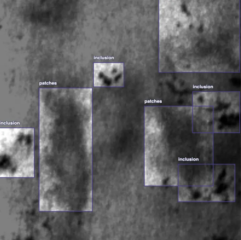
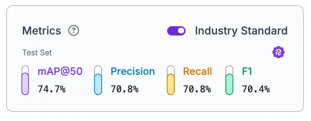
Generate a version and train an RF-DETR model through Custom Training. The model needs to detect defects reliably on individual tiles, since the Workflow will slice the strip and run inference per tile rather than on the full image at once. This run reached 74.7% mAP@50, 70.8% precision, 70.8% recall, and 70.4% F1.
Build the Synthetic Test Strip
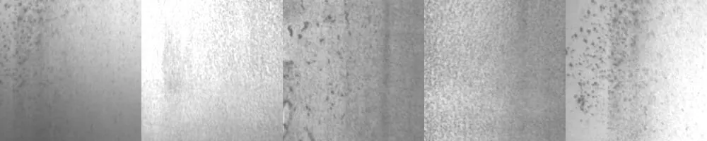
The dataset contains individual 200x200 images, not the long continuous strips a line scan camera would produce. To test the full SAHI (Slicing Aided Hyper Inference) pipeline, we'll create a script `create_strip.py` that stitches a handful of test images side by side into a single horizontal strip, simulating what a line scan camera would output.
from PIL import Image
import os


folder = "test_images"
images = sorted([
   os.path.join(folder, f)
   for f in os.listdir(folder)
   if f.lower().endswith((".jpg", ".jpeg", ".png"))
])


frames = [Image.open(img) for img in images]


height = frames[0].height
total_width = sum(f.width for f in frames)


strip = Image.new("RGB", (total_width, height))


x = 0
for frame in frames:
   strip.paste(frame, (x, 0))
   x += frame.width


strip.save("synthetic_strip.jpg", quality=95)
print(f"Saved synthetic_strip.jpg ({total_width}x{height})")
Pull 5 to 10 images from your test set into a folder called `test_images` (or update the `folder` variable in the script to match whatever name you use), run the script, and it produces a single `synthetic_strip.jpg` that concatenates them edge to edge into one long image. The strip is intentionally synthetic and the seams between images will be visible, but that's fine for demonstrating the tiling and boundary-handling pipeline, which is what matters here.
Detect Defects in Line Scan Images with Roboflow Workflows
The entire tiling, inference, and merging pipeline fits into three core blocks that Roboflow Workflows provides natively: Image Slicer, your detection model, and Detections Stitch. No Custom Python Blocks, no external scripts. Here's the workflow we'll build.
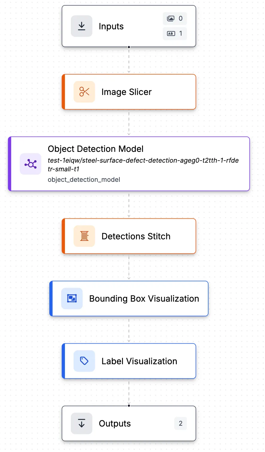
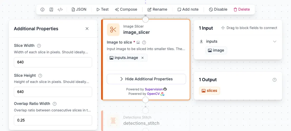
Image Slicer takes the full strip and cuts it into overlapping tiles. Set the slice width and height to match what the model expects, 640x640 in this case, and set the overlap ratio to 0.25. That 25% overlap means each tile shares a quarter of its width with its neighbor, enough margin to guarantee that any defect sitting on a boundary appears fully inside at least one tile.
The Object Detection Model receives slices from the Image Slicer, not the original strip. It runs RF-DETR on each tile individually, producing a separate set of detections per tile. From the model's perspective, each tile is just a normal-sized image.
Detections Stitch is where the boundary problem gets solved. It takes the model's per-tile predictions and the original strip image as a reference, remaps every detection's coordinates from tile-local space back to the full strip's coordinate system, then applies NMS with an IoU threshold of 0.5 to remove duplicates from the overlap zones.
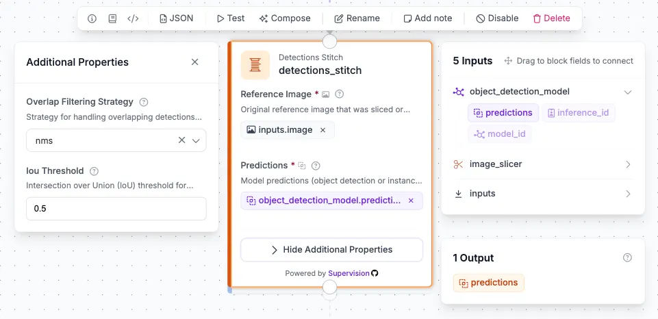
From there, Bounding Box Visualization and Label Visualization draw the final, deduplicated detections on the original full strip image, and the Outputs block returns the annotated strip alongside the merged prediction list.
Results
Feed the synthetic strip into the Workflow and the full pipeline runs in a single pass: Image Slicer tiles it, RF-DETR runs on each tile, and Detections Stitch merges everything back onto the original image.
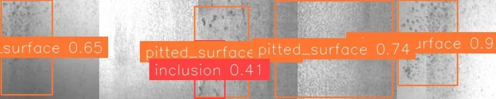
The output shows detections placed correctly across the full length of the strip, with class labels and confidence scores on each one. Defects near tile boundaries, which would have been split in half or missed entirely without overlap, appear as single, clean bounding boxes rather than duplicated or partial detections. That's the Detections Stitch block doing its job: remapping tile-local coordinates back to the strip and merging any duplicates from the overlap zones into one detection each.
Build Your Line Scan Inspection Pipeline with Roboflow
Roboflow Workflows makes it straightforward to apply object detection to long inspection images while preserving the detail small defects need. Image Slicer creates overlapping tiles, RF-DETR detects defects within each tile, and Detections Stitch brings the predictions back into the original image’s coordinates while filtering duplicate detections.
To adapt this tutorial to your production line, replace the synthetic strip with real inspection images and use a model trained on your materials and defect classes. Check detections against reference inspections, paying particular attention to defects near tile boundaries. Adjust tile size, overlap, and confidence thresholds to balance detection quality with processing time.
Build your inspection pipeline in Roboflow Workflows and test the complete process on your own images.
Further reading