Brazing Joint Inspection AI
Catch the incomplete fillet at the brazing station, not at the leak test with a finished coil built around it.
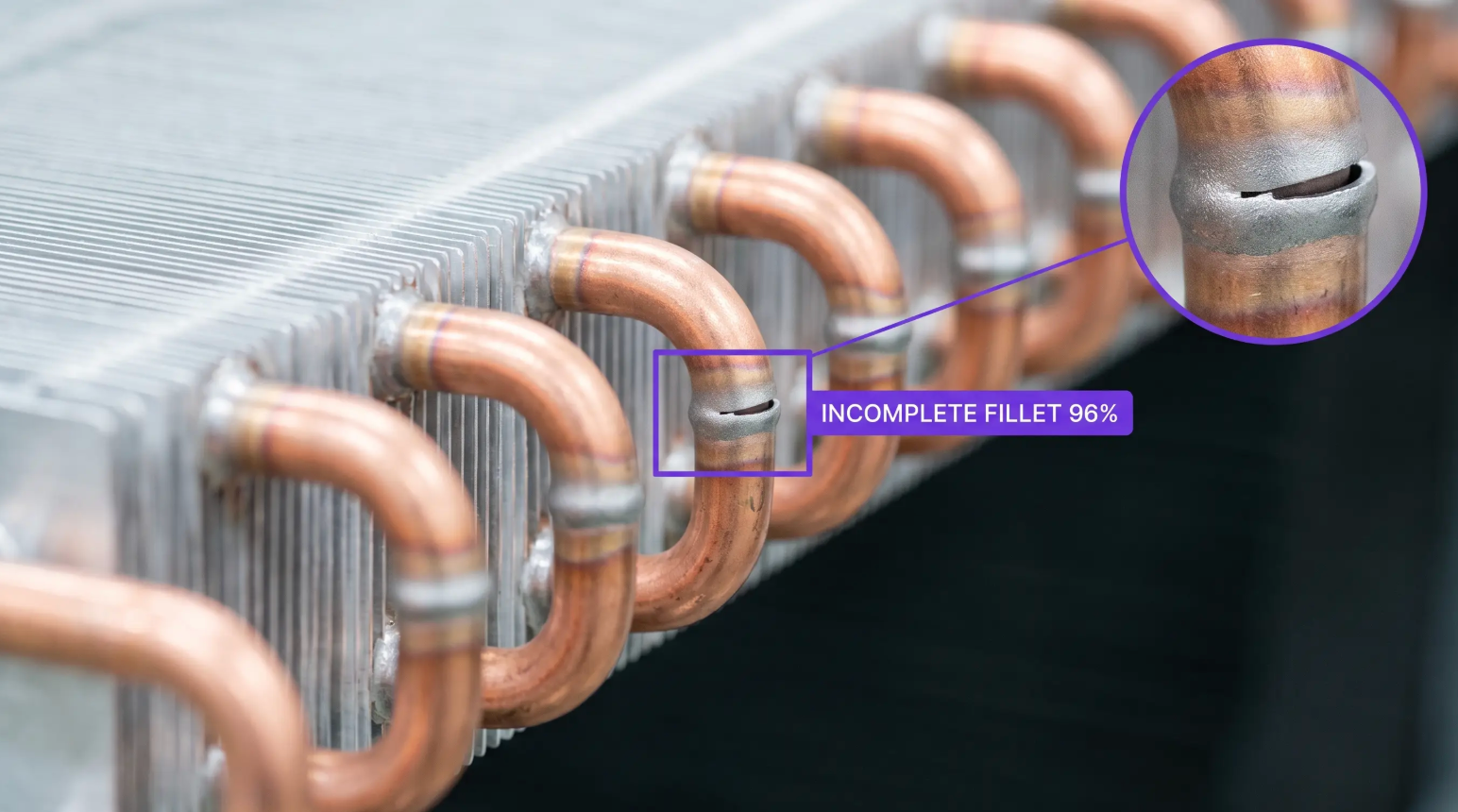
Brazing Joint Inspection AI Across Coils, Headers, Tube Assemblies, and Instruments
Deploy Anywhere, Run Everywhere
Run brazing joint inspection at the brazing station, on post-braze conveyor cameras, in robotic braze cells, the edge, on-prem, in your VPC, or via API, wherever your coil lines, tube shops, and assembly cells need it.
One Platform, Full Adoption
Tools every manufacturing organization can adopt, from braze operators and process engineers to quality leads and reliability engineering, no separate ML team required to ship and own inspection models.
Secure, Compliant, and Audit-Ready
Data stays safe with SOC 2 Type II compliance, encrypted data, and an uptime SLA, with per-joint records that support AWS B2.2 brazing procedure qualification, ASME Section IX Part QB, ISO 13585 brazer qualification, and ISO 9001 or ISO 13485 quality programs.
- Fillet Formation & Coverage
- Voids, Porosity & Blowholes
- Insufficient & Excess Filler
- Overheat, Oxidation & Burn Signatures
- Insertion Depth & Joint Alignment
- Per-Joint Records Before Leak Test
“Roboflow has been instrumental in accelerating our deployment of innovative AI solutions.”
Travis Turnbull
Vice President & CIO, Pella Corporation
Talk to a vision AI engineer who's shipped brazing joint inspection on live coil lines.
A fillet that never closed on the back side of a return bend, a joint the operator ran hot into a sooty ring while the filler never wetted, or a distributor tube seated a quarter inch short can mean a coil that fails pressure decay after the whole assembly is built around it, a refrigerant leak that surfaces as a warranty callback in year two, or an A2L charge escaping a system that was never supposed to leak. Bring us your toughest brazing joint inspection problem and we'll map a working solution.
Ask us about:
- Solution architecture for AWS B2.2 and C3.4 brazing qualification, ASME Section IX Part QB, ISO 13585 brazer qualification, and ISO 9001 or ISO 13485 quality systems
- Live demo on your own joint imagery, across your filler metals, tube diameters, and joint geometries
- Deployment options: brazing station and post-braze cameras, robotic braze cells, edge, on-prem, air-gapped, or VPC, with integration into MES, traceability, and leak-test routing
- ROI modeling against pressure-decay failure rate, rework and scrap on assembled coils, warranty leak claims, and refrigerant loss
Over 16,000 organizations build with Roboflow.
- Rivian
- Pella
- Chobani
- USG Corporation
- BNSF Railway
- American Woodmark
Vision AI is transforming businesses
Customers across the board are solving complex challenges and driving meaningful impact.
- Automotive customer
$10 million
Saved by automatically detecting defects on the production line
- Logistics & freight company
90%
Less time spent manually tracking shipping inventory
- Building materials supplier
60%
Lower customer return rate with improved product quality